The Honeywell Pro 8000 system offers robust control and integration capabilities, detailed in available programming software tools and cabling guides.
System Overview and Components
The Honeywell Pro 8000 system is a comprehensive security and automation platform, designed for both residential and commercial applications. Core components include the control panel itself, field devices like sensors and detectors, and a user interface for system control.
Communication relies on wired and wireless technologies, enabling flexible installation options. IPC 8000 cabling configurations are crucial for reliable operation, as detailed in specific documentation. The system integrates with various Honeywell products, such as thermostats (like the Nest Learning Thermostat) and potentially other building automation systems.
Further components may include power supplies, backup batteries, and communication modules. Understanding the interplay of these elements is vital for successful installation and ongoing maintenance, referencing guides like the 3rd Gen Thermostat Welcome Guide for related insights.
Intended Use and Applications
The Honeywell Pro 8000 system serves as a central hub for security, access control, and building automation. Its primary intended use is to protect premises from intrusion, fire, and other hazards, offering peace of mind to property owners and occupants.
Applications span a wide range, from safeguarding homes and small businesses to managing larger commercial facilities. It can be integrated with life safety systems, providing a unified platform for emergency response. The system’s adaptability allows for customized configurations to meet specific needs, potentially including integration with aviation systems as referenced in related publications.

Furthermore, it supports remote monitoring and control, enhancing convenience and responsiveness. Detailed manuals and guides, like those for Quattroclima systems, highlight the importance of proper installation for optimal performance.
Safety Precautions
Always disconnect power before wiring. Follow electrical safety requirements and consult installation manuals for proper grounding and component handling procedures.
General Safety Guidelines
Prior to commencing any installation or maintenance work on the Honeywell Pro 8000 system, a thorough review of all available documentation is essential. This includes, but isn’t limited to, the installation manual, programming guides, and any supplemental safety bulletins issued by Honeywell. Qualified personnel, possessing appropriate training and experience, should exclusively perform all work.
Always de-energize the system before making any connections or disconnections. Verify the power is off using appropriate testing equipment. Wear appropriate personal protective equipment (PPE), including safety glasses and insulated gloves. Be mindful of potential hazards such as sharp edges and pinch points. Ensure the work area is clean, well-lit, and free of obstructions. Proper labeling of wires and components is crucial for safe and efficient operation.
Electrical Safety Requirements
Strict adherence to all applicable national and local electrical codes is mandatory during the installation of the Honeywell Pro 8000 system. All wiring must be performed by a licensed electrician, ensuring compliance with relevant safety standards. Verify the power supply voltage matches the system requirements before making any connections. Proper grounding is critical to prevent electrical shock and ensure system stability.
Use only approved wiring methods and materials, suitable for the intended application. Never overload circuits or use damaged wiring. Implement appropriate overcurrent protection, such as fuses or circuit breakers, to safeguard against electrical faults. Regularly inspect all electrical connections for tightness and damage. Disconnect power before any inspection or repair work.

Pre-Installation Checklist
Before beginning, confirm all necessary tools are available and verify the package contents match the provided documentation for a smooth setup.
Tools Required for Installation
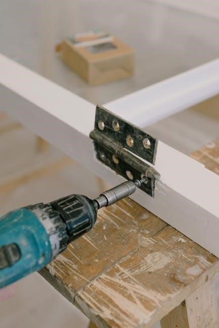
Successful installation of the Honeywell Pro 8000 system necessitates a specific set of tools to ensure accuracy and safety. Essential items include a standard screwdriver set, encompassing both Phillips and flathead options, for securing the control panel and field devices. Wire strippers are crucial for preparing wiring connections, while a wire crimper guarantees secure terminations.
A multimeter is indispensable for verifying power supply voltages and continuity of wiring. Additionally, a drill with appropriate bits will be needed for mounting the control panel to the designated location. Consider having a level handy to ensure proper alignment during mounting. Finally, network cabling tools, such as RJ45 crimpers and cable testers, may be required depending on the communication configuration.
Verifying Package Contents
Upon receiving the Honeywell Pro 8000 package, a thorough verification of contents is paramount before commencing installation. Carefully inspect the packaging for any signs of damage incurred during shipping. The package should include the Pro 8000 control panel itself, a comprehensive installation and operational manual, and potentially, mounting hardware such as screws and anchors.
Check for the presence of any specified field devices or modules ordered alongside the control panel. Refer to the packing list to confirm all components are accounted for. Note any discrepancies immediately and contact the supplier. Ensure all included documentation, like programming software access details, are present and undamaged to avoid delays during setup.

Mounting the Pro 8000 Control Panel
Securely mounting the Pro 8000 is crucial for stable operation. Consider location carefully, ensuring accessibility for wiring and future maintenance procedures.
Location Considerations
Selecting an appropriate location for the Pro 8000 control panel is paramount for optimal system performance and longevity. Prioritize a clean, dry, and well-ventilated environment, shielded from extreme temperatures and direct sunlight. Accessibility is key; technicians will require convenient access for routine maintenance, troubleshooting, and future system upgrades.
Avoid areas prone to excessive dust, moisture, or vibration, as these can compromise the panel’s internal components. Ensure sufficient space around the unit for proper airflow and wiring connections. Consider proximity to the power source to minimize cabling distances. The mounting surface must be structurally sound and capable of supporting the panel’s weight, preventing potential instability or damage.
Physical Mounting Procedure
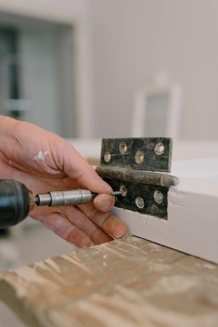
Begin by securely attaching the mounting plate to the chosen surface, utilizing appropriately sized screws and anchors suitable for the wall material. Ensure the plate is level to guarantee proper panel alignment. Carefully align the Pro 8000 control panel with the mounted plate, gently guiding it into position.
Secure the panel to the plate using the provided screws, tightening them firmly but avoiding over-tightening, which could damage the enclosure. Verify the panel is firmly affixed and does not exhibit any wobble or instability. Double-check all screw connections to ensure a secure and lasting mount. Proper physical installation is crucial for reliable operation.

Wiring and Connections
Proper cabling configurations, as detailed in IPC 8000 guides, are essential for successful system integration and reliable communication between devices.
Power Supply Connections
Establishing secure and correct power supply connections is paramount for the reliable operation of the Honeywell Pro 8000 system. Refer to the detailed installation manuals and cabling guides for specific voltage and amperage requirements, ensuring compatibility with your local power infrastructure.
Carefully observe polarity when connecting power sources to avoid damaging the control panel or connected field devices. Improper connections can lead to system malfunction or even pose a safety hazard. Utilize appropriately sized wiring and secure connections to minimize voltage drop and ensure stable power delivery.
Always verify power supply voltage before connecting the system, and consider employing surge protection devices to safeguard against power fluctuations and transient events. Following these guidelines will contribute to a stable and long-lasting installation.
Field Device Wiring Diagrams
Accurate field device wiring is crucial for seamless integration with the Honeywell Pro 8000 control system. Detailed wiring diagrams, found within the installation documentation and cabling guides, illustrate the correct connections for various sensors, actuators, and communication modules.
Pay close attention to terminal designations and wiring configurations, as incorrect wiring can lead to inaccurate readings, malfunctioning devices, or system instability. Utilize appropriate wire gauges and secure connections to ensure reliable signal transmission.

Refer to the specific device manuals for detailed wiring specifications and compatibility information. Proper implementation of these diagrams guarantees optimal system performance and minimizes troubleshooting efforts during commissioning and maintenance.

Programming the Pro 8000
Accessing the programming interface requires specific software tools, enabling configuration of system parameters and defining operational logic for optimal performance.
Accessing the Programming Interface
To begin programming the Honeywell Pro 8000, dedicated software tools are essential. These tools, often downloadable as PDF files or accessible through specific applications, provide a user-friendly environment for system configuration. The software facilitates establishing communication with the control panel, allowing technicians to upload and modify programming parameters.
Initial access typically involves connecting a computer to the Pro 8000 panel via a designated port, often utilizing a USB or serial connection. Once connected, the software will guide you through the process of identifying the panel and establishing a secure communication link. Proper software installation and driver configuration are crucial for seamless connectivity. Refer to the software documentation for detailed instructions on establishing this initial interface.
Basic Programming Parameters
Fundamental programming involves defining core system settings. This includes configuring communication parameters to ensure reliable data transmission between the control panel and connected devices. Establishing accurate date and time settings is also critical for event logging and scheduling functions.
Zone configuration is a primary step, defining each protected area and its associated sensors. Point types, such as normally open or normally closed, must be correctly assigned to each input. Furthermore, programming includes setting response parameters – how the system reacts to alarm triggers, including entry/exit delays and siren activation durations. Careful attention to these basic parameters ensures optimal system performance and reliability.

System Configuration
Proper configuration necessitates defining zones and communication settings, ensuring seamless integration and reliable operation of all connected field devices within the network.
Defining Zones and Points
Establishing clearly defined zones is crucial for effective system management. Each zone represents a specific area or grouping of sensors and devices, allowing for targeted monitoring and control. Points, representing individual sensors or outputs, must be accurately assigned to their corresponding zones.
This meticulous process ensures that alarm events are correctly identified and reported, enabling swift and appropriate responses. Careful consideration should be given to the physical layout of the protected premises when defining zones, grouping similar devices together for streamlined operation. Proper point assignment is vital for accurate system functionality and reliable performance, as detailed in the system’s programming documentation.
Communication Settings
Configuring communication settings is paramount for reliable system operation and remote access. The Honeywell Pro 8000 supports various communication protocols, requiring careful parameterization to ensure seamless connectivity. This includes defining the appropriate baud rate, parity, and communication port settings for each connected device.
Proper network configuration is also essential, assigning unique IP addresses and gateway information as needed. Secure communication protocols should be implemented to protect against unauthorized access and data breaches. Detailed documentation outlines the specific communication requirements for each supported device, ensuring optimal performance and system integrity. Verification of these settings is crucial during the initial system setup.

Testing and Troubleshooting
Initial system tests verify proper functionality, while troubleshooting guides address common issues like communication failures or incorrect parameter settings.
Initial System Test
Following installation, a comprehensive system test is crucial for verifying correct operation of the Honeywell Pro 8000. Begin by powering up the control panel and confirming the display initializes without errors. Walk-test each zone individually, activating sensors and verifying corresponding alarm signals are received and processed by the panel.
Check communication pathways to ensure the panel reliably connects with any connected field devices or central monitoring stations. Review programmed parameters against the intended system configuration, confirming zone definitions, communication settings, and user access levels are accurate. Document all test results, noting any discrepancies or failures encountered during the process. Addressing these issues promptly ensures a secure and reliable system.
Common Troubleshooting Steps
When encountering issues with the Honeywell Pro 8000, begin with basic checks. Verify power supply connections and ensure adequate voltage is reaching the control panel. Inspect all wiring for loose connections or damage, paying close attention to field device terminations. Review programming parameters for errors in zone definitions or communication settings.
If communication failures occur, confirm network connectivity and check for interference. For alarm issues, re-test sensors and verify their proper functionality. Consult the installation manual and available documentation for specific error codes or troubleshooting guidance. If problems persist, contact Honeywell technical support for assistance, providing detailed information about the issue and steps already taken.